All-Welded Attached to Supporting Clip Angles
- General Overview
- Tips and Tricks
- Related Tools
To specify this type of standard clip angle in the model :
- All-Welded Attached to Supporting Clip Angles are double clip angles that shop attach to the supporting member (beam or column). They are designed as the supported beam's end connection when ' Supporting ' (shop attached to), ' Welded ' (to supported) and ' Welded ' (to supporting) are set in "
 Connection specifications " for auto standard , user defined or beam-window-specified clip angles.
- For a joist, the required settings that result in a clip angle being designed using this clip angle configuration are ' Welded ' (to supported) and 'Welded' (to supporting).
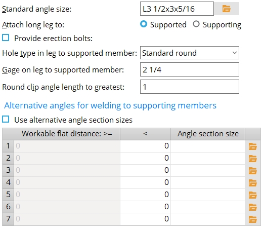
Standard angle size: The preferred angle section size . The angle must be listed in the local shape file. Note that alternative angles can also be specified on this window.
To enter an angle section size: Either type in the section size that you want (e.g., ' L4x3 1/2x5/16 '), or press the "file cabinet" browse button (
) and choose an angle section from the list of angles in the local shape file .
Attach long leg to: Supported or Supporting . This applies when a " Standard angle size " with unequal legs has been entered.
' Supported ' field welds the long leg of the angle to the supported beam or joist. Erection bolts can also, optionally, be provided for field bolt attachment of the to-supported leg.
' Supporting ' fastens the long leg of the angle to the supporting beam or column.
Provide erection bolts: ![]() or
or ![]() . This sets whether or not erection bolts are provide when ' Automatic ' is the choice made to " Use erection bolts " in the
. This sets whether or not erection bolts are provide when ' Automatic ' is the choice made to " Use erection bolts " in the ![]() Connection specifications "
Connection specifications "
If this box is checked (
), erection bolts are provided. For a beam end connection that is not auto standard, the bolts are the "
If the box is not checked (
), the All-Welded Attached to Supporting Clip Angles clip angles are designed without erection bolts.
Hole type in leg to supported member: Standard round or Short slot or Long slot or Oversized or User slot #1 or User slot #2 .

Gage on leg to supported member: The distance from the outside corner of the clip angle to the center of the column of holes for erection bolts to the supported beam or the knife plate of the joist.
Round clip angle length to greatest: The distance that you want connection design to increment the length of clip angles (e.g., 1/2 makes connection design round angle length up to the nearest half inch).
Alternative angles for welding to supporting members
Use alternative angle section sizes: ![]() or
or ![]() .
.
If this box is checked (
If the box is not checked (
Workable flat distance is greater than or equal to
( >= )Workable flat distance is less than
( < )Angle section size The values in the first column are filled in automatically. They represent the lowest workable flat distance at which the " Angle section size" entered in a particular row will be applied.
The values in the second column can be filled in manually. Each such value represents the largest workable flat distance at which the " Angle section size " entered in a particular row will be applied. The angle to be welded within the workable flat distance on the supporting member. You need to account for the welds and the thickness of the supporting beam's web as well as the angle leg size when determining if the angle will fit in the specified workable flat distance.


|
|
OK (or the Enter key) closes this screen and applies the settings.
Cancel (or the Esc key) closes this screen without saving any changes.
Reset undoes all changes made to this screen since you first opened it. The screen remains open.
- Settings applied here are for your current Fabricator . Each Fabricator in your current Job is a different collection of settings.
- To edit the Clip Angle Piecemarks table on this screen, your current Fabricator must be the Master Fabricator, otherwise this table is disabled .
- If your current Fabricator is not the Master Fabricator, the piecemarking routine will continue to reference the version of the Clip Angle Piecemarks table in the Master Fabricator.
- If the Clip Angle Piecemarks table on this screen is filled out, any standard piecemark from the table can be added as an existing material .
- Red or yellow exclamation point icons
 or
or 
- Clip angle input specs (settings for clip angles)
- Setup of clip angle connections (index)
- Clip Angle Settings

